Power Transformers, Distribution Transformers & Voltage Regulation Equipment
Technical White Paper & O&M Reference Guide
1. Introduction & Purpose
This document serves as a comprehensive Installation, Operation, and Maintenance (IOM) Manual for PowerNex transformers and voltage regulation equipment. It is intended to support safe installation, reliable operation, preventive maintenance, and long-term asset management throughout the complete service life of the equipment.
Transformers are long-life assets typically designed for 25–40 years of continuous operation. Achieving this design life depends not only on manufacturing quality, but also on correct installation, operating discipline, environmental control, and systematic maintenance. This manual consolidates international standards, industry best practices, and field-proven engineering experience from global PowerNex installations.
Applicable Standards & References
-
IEC 60076 / IEC 61936 (Power and Distribution Transformers)
-
IEEE C57 Series (Design, Testing, and Loading Guides)
-
ANSI / NEMA Standards
-
NEC (NFPA 70) Electrical Code
-
UL / CE Certification Requirements
-
Local utility and regulatory requirements
2. Equipment Scope & Applications
This manual applies to the following PowerNex equipment categories, covering a wide range of power ratings from tens of kVA to hundreds of MVA, and voltage classes from low voltage up to high voltage transmission levels:
-
Oil-Immersed Power Transformers (ONAN, ONAF, OFAF)
-
Oil-Immersed Distribution Transformers
-
Dry-Type Transformers (Cast Resin & VPI)
-
Pad-Mounted Transformers and Unit Substations
-
Isolation and Special Purpose Transformers
-
Automatic Voltage Regulators (Servo and Static Type)
-
Renewable Energy Transformers (Solar PV, Wind, and BESS)
Applications include industrial plants, substations, data centers, commercial buildings, renewable energy plants, mining operations, and critical infrastructure. Each application may introduce specific thermal, harmonic, environmental, or reliability requirements, which must be addressed during engineering and installation.
3. Safety Philosophy & Risk Management
3.1 General Safety Principles
Transformers operate with high voltage, high fault current, and significant stored magnetic and thermal energy. Even after de-energization, residual energy may remain in windings, capacitors, or magnetic circuits.
-
Only trained and authorized personnel may install or service equipment
-
Lockout/Tagout (LOTO) procedures must be enforced at all times
-
Barriers, signage, and restricted access zones should be clearly defined
Industry data shows that human error and procedural violations remain among the most common causes of electrical accidents. Strict adherence to procedures significantly reduces risk.
3.2 Personal Protective Equipment (PPE)
Minimum PPE typically includes:
-
Arc-rated clothing appropriate to calculated incident energy
-
Insulated gloves rated for system voltage
-
Safety footwear with dielectric protection
-
Face shields, eye protection, and hearing protection
PPE selection should be based on arc flash studies and site-specific risk assessments, not generic assumptions.
4. Pre-Installation Engineering & Site Preparation
4.1 Environmental & Electrical Design Review
Before installation, perform a detailed design review to confirm:
-
Rated voltage, frequency, insulation class, and cooling method match the system
-
Ambient temperature (often 40°C standard) and altitude corrections are applied
-
Short-circuit withstand capability exceeds system fault levels
-
Harmonic content and non-linear loads are considered
High harmonic environments such as data centers or VFD-driven systems may require K-factor rated transformers or derating by 10–30%.
4.2 Civil & Structural Requirements
-
Foundations must withstand static weight plus dynamic forces from short-circuit events
-
Oil containment systems should be sized to retain 100% of oil volume
-
Fire separation distances and fire barriers must comply with local codes
Structural deficiencies are a common source of vibration, noise transmission, and long-term mechanical stress.
5. Transportation, Storage & Handling
5.1 Transportation Guidelines
-
Maintain upright orientation unless specified otherwise
-
Shock, tilt, and impact indicators should be reviewed upon receipt
-
Long-distance transport may require re-tightening of mechanical connections
5.2 Storage Prior to Installation
-
For storage exceeding 6 months, periodic insulation resistance testing is recommended
-
Oil-filled units should maintain positive internal pressure and sealed condition
-
Moisture ingress during storage is a major contributor to reduced dielectric strength
6. Installation Procedures
6.1 Mechanical Installation
-
Verify transformer level within manufacturer tolerances (often ≤ 1 mm/m)
-
Confirm removal of all transport restraints
-
Ensure proper alignment of bushings and cable terminations
6.2 Grounding & Bonding
-
Ground resistance typically should not exceed 1 ohm, subject to system design
-
Neutral grounding methods (solid, resistor, or reactance grounding) must match system studies
-
Improper grounding can lead to protection malfunction and elevated touch voltage
6.3 Electrical Connections
-
Verify vector group and phase displacement before energization
-
Use calibrated torque tools and record torque values
-
Poor terminations account for a significant portion of overheating failures
7. Cooling Systems & Thermal Management
7.1 Oil-Immersed Transformers
-
Verify fan start temperatures and alarm setpoints
-
Clean radiators periodically to maintain heat transfer efficiency
-
Elevated oil temperature accelerates insulation aging exponentially
7.2 Dry-Type Transformers
-
Ensure minimum air clearances per IEC/IEEE recommendations
-
Dust accumulation can reduce cooling efficiency by over 20%
-
Enclosure design directly affects thermal performance
8. Commissioning & Acceptance Testing
8.1 Mandatory Pre-Energization Tests
-
Insulation Resistance and Polarization Index
-
Winding Resistance (temperature corrected)
-
Ratio, Polarity, Vector Group
-
Oil dielectric strength and moisture content
-
Protection relay logic and interlock testing
Test records form the baseline condition reference for the entire service life.
9. Normal Operation Guidelines
-
Maintain loading below nameplate rating for continuous operation
-
Monitor load balance; imbalance above 10% may cause localized overheating
-
Sudden noise or temperature changes require immediate investigation
10. Preventive & Predictive Maintenance
10.1 Routine Maintenance
Routine inspections focus on early visual and operational indicators of deterioration.
10.2 Condition-Based Maintenance
Modern diagnostics allow maintenance based on equipment condition rather than calendar time, improving reliability and reducing cost.
10.3 Major Maintenance Intervals
Major inspections are typically performed every 3–5 years, depending on operating conditions.
11. Failure Modes & Troubleshooting
| Condition | Possible Cause | Mitigation |
|---|---|---|
| Overheating | Overload, cooling failure | Load reduction, cooling repair |
| Excessive noise | Core saturation, harmonics | Voltage/load review |
| Insulation aging | Moisture, thermal stress | Drying, oil treatment |
| AVR instability | Control system fault | Calibration or repair |
12. Environmental & Sustainability Considerations
-
Spill prevention and containment planning
-
Use of ester fluids can reduce fire risk and environmental impact
-
Efficiency improvements reduce lifetime CO₂ footprint
13. Asset Management & Lifecycle Extension
-
Data-driven maintenance decisions extend asset life
-
Retrofits can improve efficiency and monitoring capability
-
Replacement planning should be condition-based, not age-based
14. Technical Support & Engineering Services
PowerNex provides:
-
Installation supervision and commissioning
-
Advanced diagnostics and testing
-
Upgrade, retrofit, and life-extension solutions
15. PowerNex Engineering Commitment
PowerNex is a global transformer manufacturer and engineering partner, committed to delivering reliable, compliant, and high-performance power solutions. Our involvement extends throughout the entire equipment lifecycle, supporting safe operation, optimized performance, and long-term value.
For project-specific engineering support, contact PowerNex Technical Services.
Latest News
The Future of Power Distribution: Solid State Transformers (SST)
Introduction The Solid State Transformer (SST) is rapidly emerging as a breakthrough technology in modern [...]
Mar
How to Size a Transformer for Industrial Applications in 2026 (Complete Step-by-Step Guide)
Introduction Choosing the correct transformer size for an industrial application is one of the most [...]
Mar
Variable Frequency Power Supply: Industrial Guide to Specifications, Applications, 400Hz Systems & Frequency Conversion Solutions
A Variable Frequency Power Supply (VFPS) is a programmable AC power source designed to convert [...]
Feb
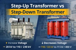
Step-Up Transformer vs Step-Down Transformer: Key Differences, Applications, and How to Choose the Right Power Solution
In modern power systems, transformers play a critical role in voltage conversion to ensure safe, [...]
Feb